Here you will find photos of some of the instrumentation.
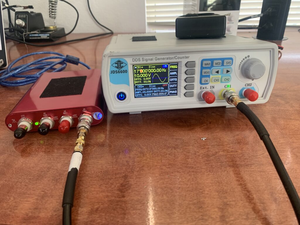
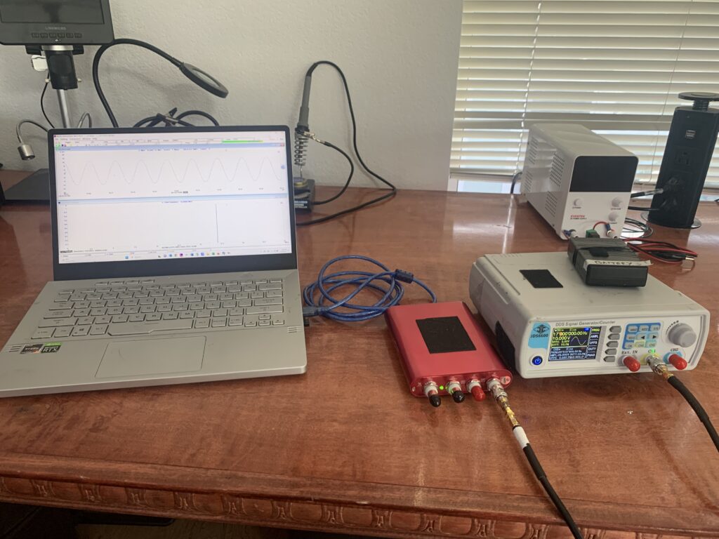
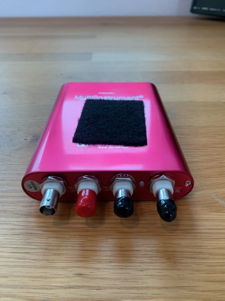
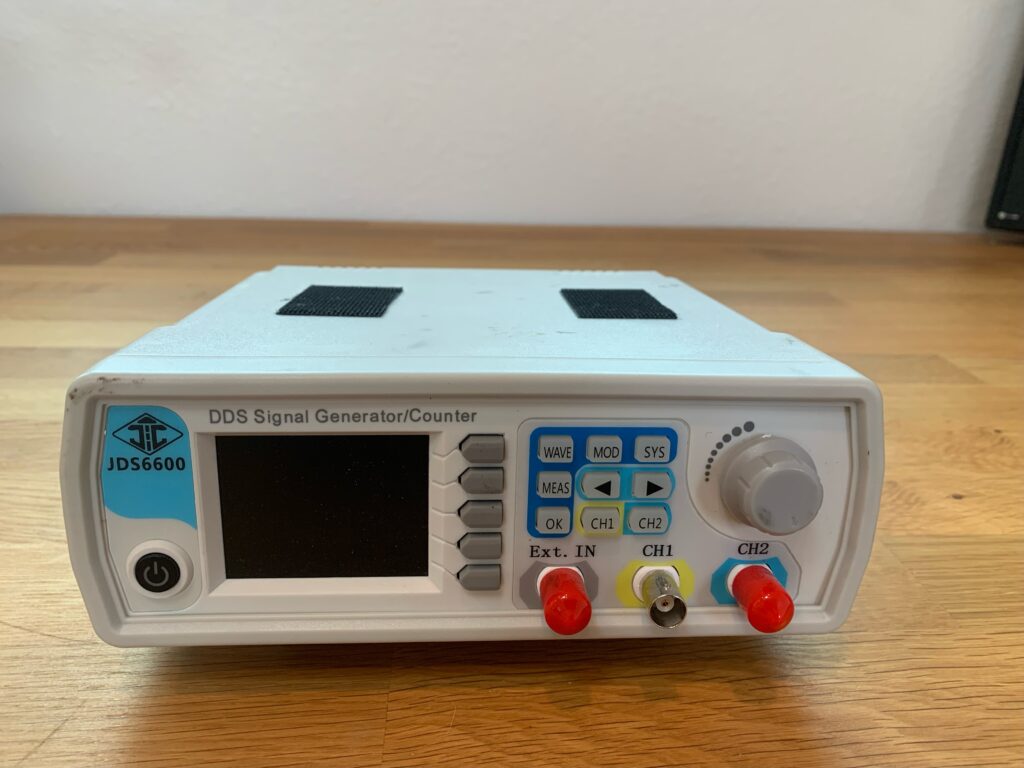
These photos are of the signal generator and USB oscilloscope used in this experiment. The signal generator has 14 bit vertical resolution. The USB Oscilloscope has 16 bit resolution.
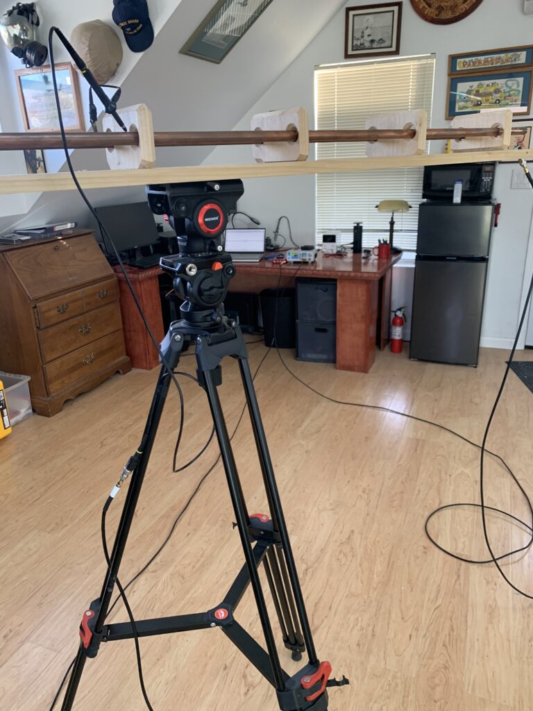
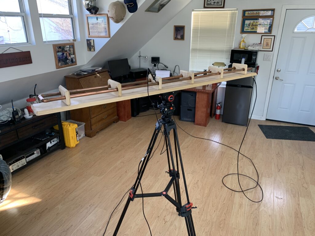
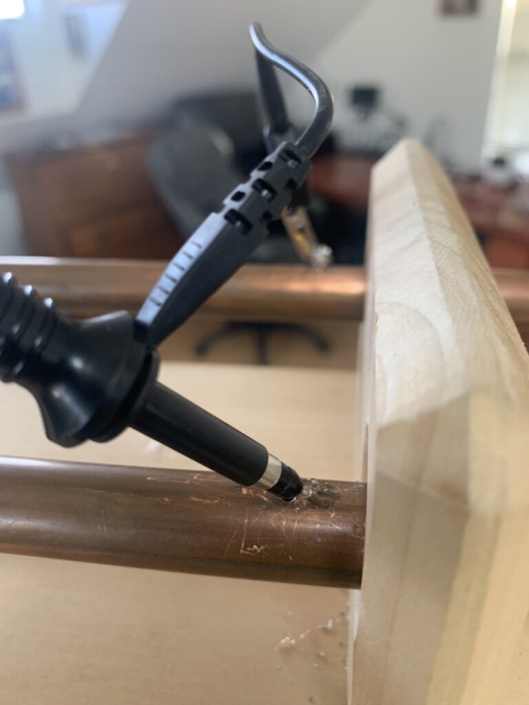
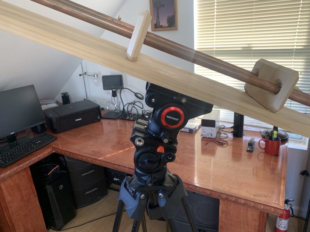
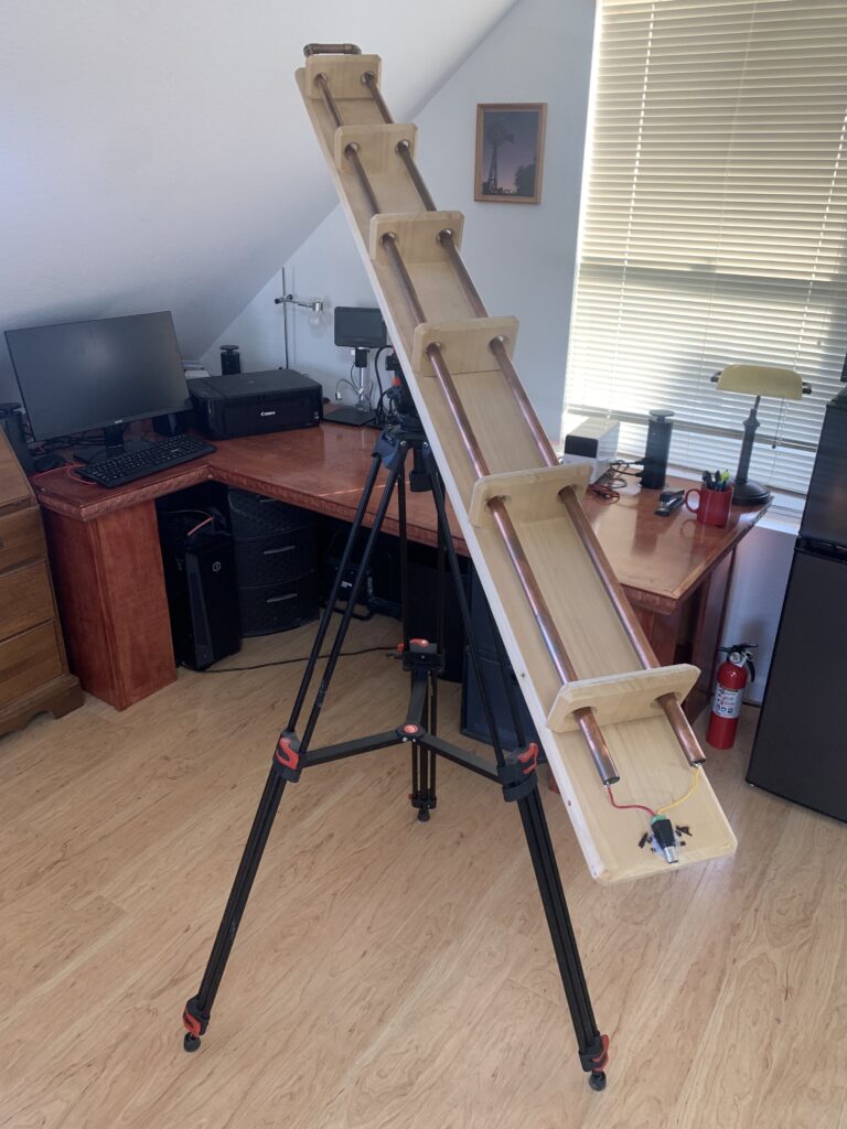
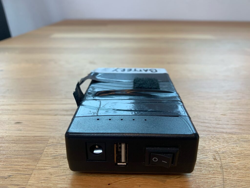
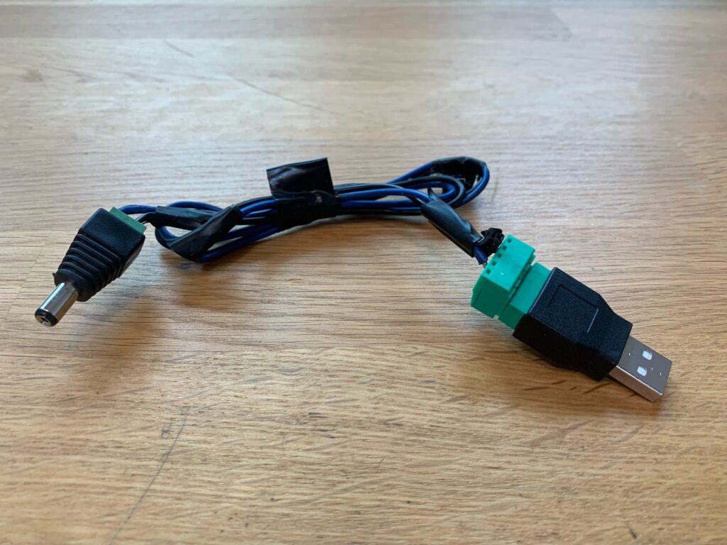
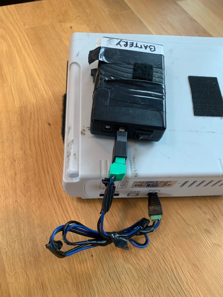
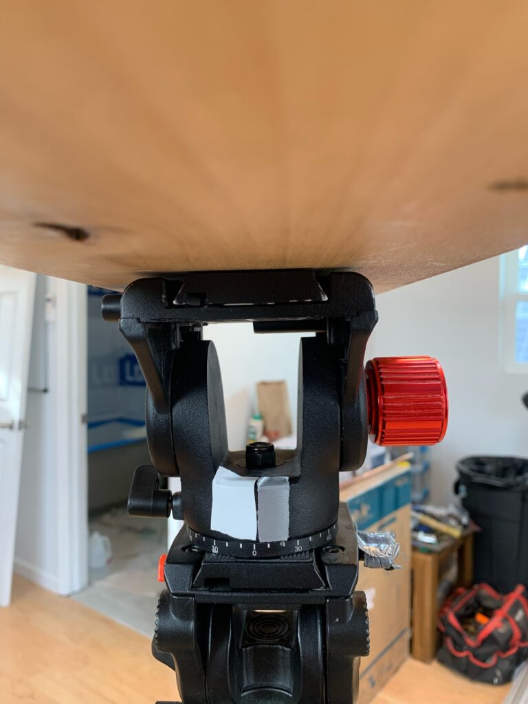
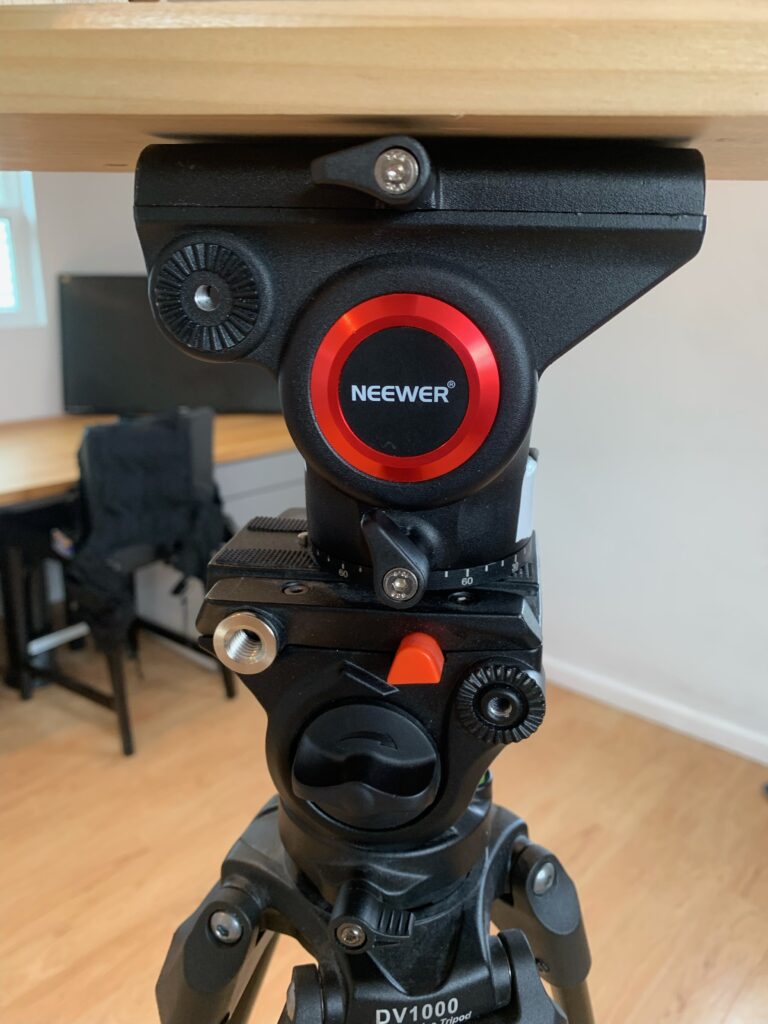
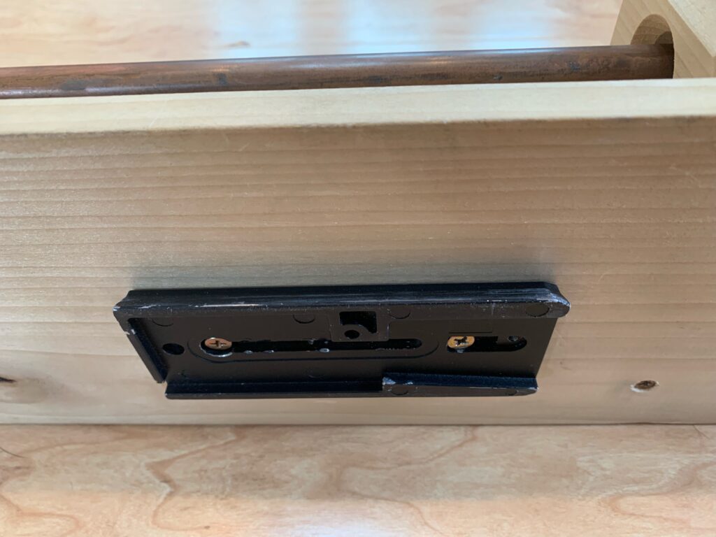
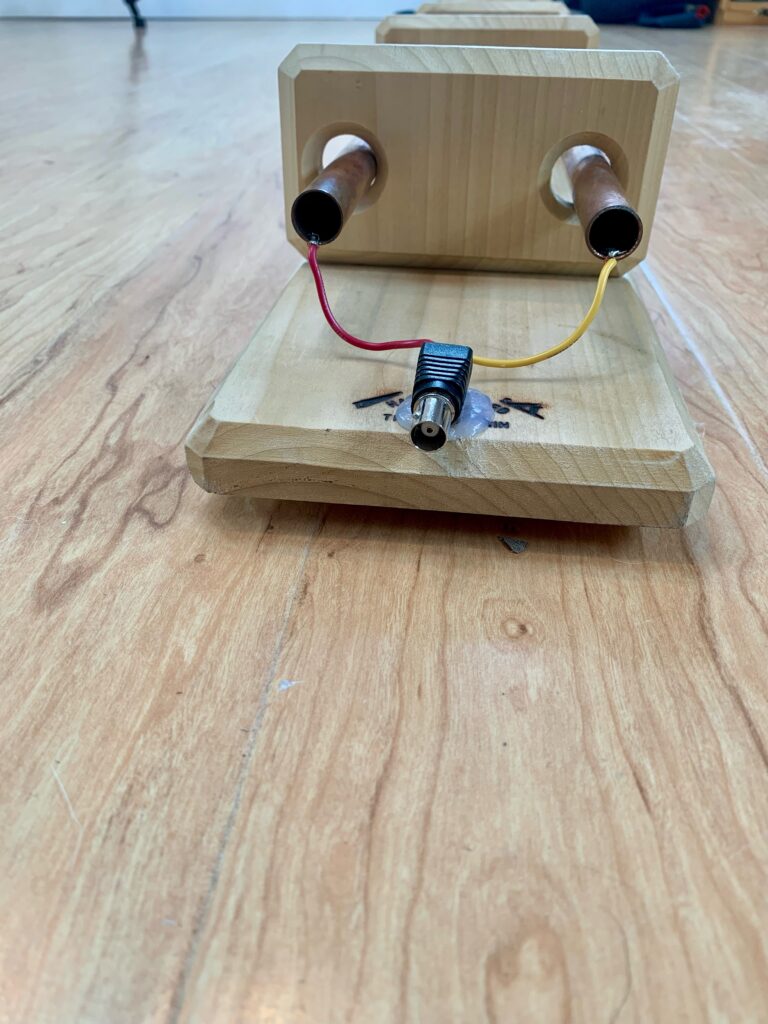
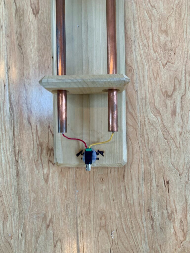
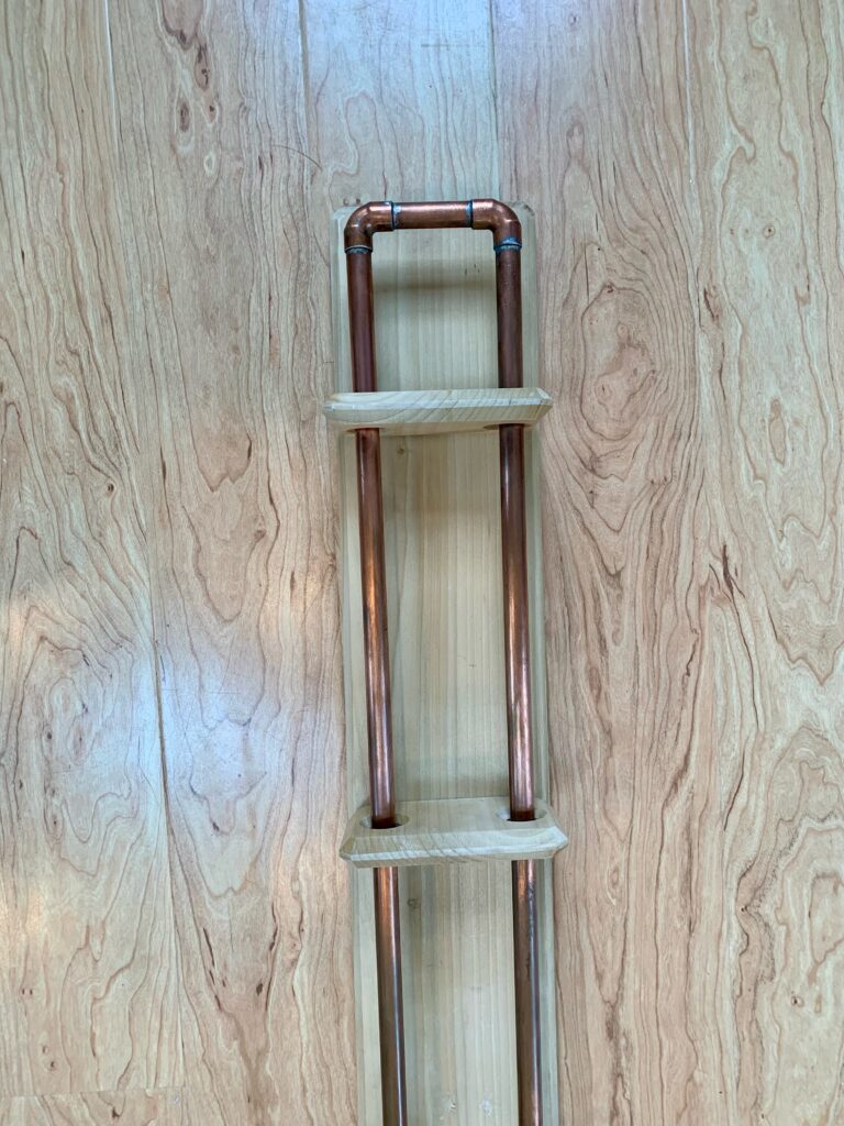
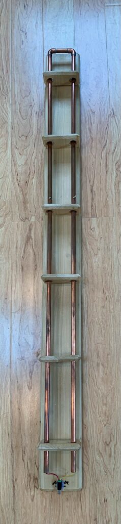
Lecher line mounted on tripodLecher line mounted on tripodsignal generator and USB oscilloscopeOscilloscope connected to laptop computer and signal generator beside it.Oscilloscope probe sitting inside drilled hole in the lecher line (Use electrical tape to keep the probe in place). In the background is the negative connect for the oscilloscope probe that connects to a “pig tail” on the opposite tube of the Lecher line. A closer look at the two tripod heads used for mounting the instrumentView of the instrument. Notice the wires connected to the end of the tubes and then connected to the BNC connectorThis is a battery I use to power the signal generatorThis is a DIY power connector to connect the USB port of the battery to the 5 volts input port for the signal generatorThe signal generator is powered by 5 volts from a transformer provided by the manufacturer. I just power it via a USB port power.This is the USB oscilloscope. The black mark is velcro.. This is the signal generatorThis is looking at the bottom of the instrument where the wood board is mounted to the tripod.A closer look at two tripod head. This is the mounting bracket for the upper tripod head. it is screwed into the wood board. This is a side view of the Lecher lineThis is looking at the back of the Lecher line with the BNC adapter provides signal to each of the pipesThis is another look at the back of the Lecher line.This is a look at the forward part of the Lecher LineThis is another look at the Lecher Line.